MG-Cars.com
Triumph TR6 Engine picture BBS discussion at MG-Cars.net

MG-Cars.net
Welcome to our resource for MG Car Information.
Recommendations
Parts
TR parts and Triumph parts, TR bits, Triumph Car Spares and accessories are available for TR2, TR3, TR3A, TR4, TR4A, TR5, TR6, TR7, TR8, Spitfire and Stag and other TR models are available from British car spares and parts company LBCarCo.
Triumph TR6 - Engine picture
| Just because I am pleased to be making some progress (and because I found out how to upload a picture for the steering rack thread!), I thought I would show you how my engine rebuild is coming along. Still a way to go, but with the head on it is looking a lot more like an engine! Cheers Alistair 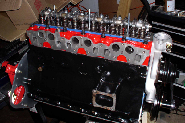 |
| A Hewitt |
| Alistair What is that rusty bolt doing in the water jacket drain hole? seriously, really looking good lad. I see you used the end plate to help mount the engine on the stand. I have always had a hankerin' for red heads:) Rickc |
| Rick Crawford |
| "What is that rusty bolt doing in the water jacket drain hole?" I went and asked it what it was doing for you. Apparently it keeps itself busy by being brass. I went to look at the paint options for the manifold last year (top tip - don't use the duplicolor spray paint for your manifold - it may have a picture of a manifold on the can but it burns off in the first few minutes) and saw the red. I decided to paint the head red then. I was tempted to paint the block red too, but I think that would be a bit much... I spent a couple of hours trying to figure out a way to mount the flywheel to the block and continue to use the stand and came up with nothing. There isn't enough clearance even using the rear plate holes. I then spent a long time trying to get the mount to be in a position where I could easily rotate the engine after adding the head and failed at that too. Not really a problem though since there is no reason I can see to rotate the engine anymore now. Just got to sort out the alternator and a bad thread in the water pump housing and I should be close to having the engine ready to go back in. Of course, I then have to clean and paint the engine bay... If you don't like the look of that water plug you shoudl probably not look at the picture of my steering rack mounts! Cheers Alistair |
| A Hewitt |
| Alistair, THAT looks really nice! One small caveat though - Scribe the paint around each cylinder head washer. Remove each nut and washer (one at a time) and scrape the paint away from under each washer. Replace the washer & nut and retorque. Move on to the next one, repeating the procedure. Otherwise once the engine heats up the paint will get soft and you may end up with head gasket leaks. Don't ask me how I know..... Tom BTW - Did I mention you're engine looks really sharp? ;o) |
| Tom Sotomayor |
| Thanks for the tip (and compliment!), Tom. On this occasion I was smart enough to mask off the area where cylinder head nut (and washer) sits. When I peeled the masking tape off I saw the size of the grey area and wondered abotu painting some or all of it, but once the washers are in place it is barely noticeable. It actually took about 90 minutes to mask off all of the machined surfaces on the head - there isn't all that much to paint! The blue line is masking tape, by the way. I wrote the rocker clearances on there since there is no way I would have kept track! The GP2 cam has different inlet and exhaust clearances. Don't ask me why. If you know, please tell me! I just got back from the machine shop where they fixed the thread in my fancy alloy water pump housing - I swear it wasn't me who damaged it! I am goign to drive over to the Roadster Factory on Saturday to drop off some of the parts I have collected (spare engine, head, diff, gearboxes, hubs etc.) so hopefully I will be able to get something sorted out to make my alternator fit while I am there. I really do think I might be on the road this summer! Cheers Alistair |
| A Hewitt |
| Hi Alistair, Fantastic job on the engine. It really looks great! I'm curious about your GP2 cam.. Was the timing of the cam to the crank pretty straight forward? I replaced mine with a stock cam and there were no instructions and the Bentley manual had some pretty funky instructions with terms like "Be sure the cam is on the rock". It took me a while but I figured out what they were talking about and got it done successfully. Have you looked into priming the oil pump system prior to start up? Be sure to post pictures after you install it. Henry |
| HP Henry Patterson |
| Henry Timing the cam and crank was the hardest part of the job (so far!). I spent several hours (maybe as much as 10 hours in all over several evenings) trying to get a sprocket/chain/cam/crank combination that worked. Actually it only took about 90 minutes or so once I spoke to Richard Good. I was foolishly assuming that the cam duration was spot on. With effort I could get one of the opening/closing figures bang on, but then the others were off. I used a dial gauge and a cardboard template to hold the push rods vertical, and I kept assumig that there must be an error in the way I was measuring. The crankshaft angle is given at 0.010" and 0.050" lift, opening and closing, for both inlet and exhaust. If I had the 0.050" inlet opening set properly, everything else was off. Then I spoke to Richard and he basically told me that the science of TR6 cam grinding is not that exact and the fact that my duration was only a few degrees off was pretty good. Once I knew that my measurements were okay I worked out the "real" duration and lift and spread it around the spec values, so all my valves open 1-2 degrees early and close 1-2 degrees late. He seemed to think that was the best approach, and by that point I was ready to sell the car for scrap so any suggestion for a relatively simple installation got my vote! I would certainly suggest that anyone thinking of changing the camshaft pull the engine out of the car. I can only imagine the back trouble I would have if all of this had been done while bending over the front wing! Hope that helps someone. If anyone wants some pictures or more details please let me know. Cheers Alistair |
| A Hewitt |
| On the subject of priming the oil system, my plan was to remove the distributor and pour oil into the hole. I figure that this should fill the pump up? I was then thinking of using an old spare distributor to turn the pump - at least until I realised that I would need to remove the distibutor drive to do this without turning the engine. That being the case, does anyone need a 1970 vintage distributor? (or pretty much anything from a 1970 engine, for that matter). My new plan is to turn the engine over with a socket on the crank pulley. I am not sure if this is better or worse than using the starter to prime things. I have read quite a few internet sites where the rebuilder has just used the starter to get the oil flowing, then installed the plugs, hook up the coil and fire it up. Any advice here? Cheers Alistair |
| A Hewitt |
| Alistair, very nice engine.... where did you acquire the cast aluminum water-pump housing? re-oil priming: assuming the engine is rebuilt using lubriplate or equiv., the engine can be primed by turning it over with the plugs out, pre-primed oil filter(spin on type). Just watch the oil gauge and the pressure should rise to about 50+psi simply by cranking it over. Remember to use GM's oil additive, EOS, from the beginning. Cheers, Rob ps here's a shot of my engine last spring...still working on the body... notice the down-pipe wrap to keep the heat off the starter, etc. 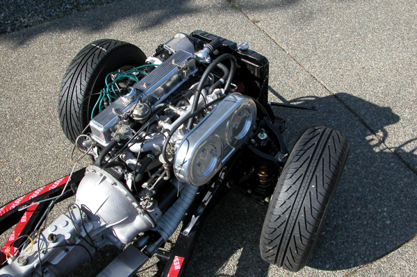 |
| Rob Gibbs |
| Alistair, Interesting story on the cam timing. I spent alot of time on mine too. The stock cam and the "Triumph" method of timing is even less of a science than what you describe. Basically they just use the fact that the cam lobes are symetrically located on the cam. In other words, the inlet and exhaust opening and closing angle degrees are the same for both. When a cylinder is at TDC of its exhaust stroke the valves should be at the exact same lift providing the designed overlap. Since the valves are at the exact same lift (cam lobes are up looking like the top of the letter "Y") the push rods will be the exact same height. The Triumph manual has you simply feeling the top of the two push rods with your palm as you rock the cam back and forth. When you feel that the rods are the same height then it's timed. As silly as it sounds it works. Instead of my palm though I used a ruler to find when both rods were equal height. As far as priming the oil system. The idea is to get all of the oil galleries full and oil squeezing out around all of the main and rod bearings prior to a start. I suppose just cranking will work but most people spin the oil pump first. I made an oil pump spinner from a bolt that I cut and polished. It fits into the distributor drive hole and is spun by a cordless drill. It worked. If you'd like I could send it to you and you could send back when done. Let me know and I'll give you my email address to get the particulars. Great learning experience isn't it? Henry |
| HP Henry Patterson |
| Alistair, If you have an old flat screwdriver laying around, just cut off the handle and put it in your drill. Run your drill backwards and you should make 90 psi. It's somehow satisfying to see the oil squeeze out of the rockers, I guess it's because mow you know you're ready to light it up. Good Luck Rob |
| rw loftus |
| Rob Gibbs - that looks great - now you have me wishing I had taken the body off the chassis... Not too practical with a single garage, though! The alloy water pump housing is from Rimmer Bros - I made a detour (I figured 30 minutes - more like 4 hours!) on a recent business trip when they had a sale going, so with the VAT claimed back it cost about $75, which is a quarter of the cost over here! At that price I wondered about buying half a dozen and selling them over here. It then cost another $10 to have a machine shop fix the bad thread - it looks nicely cast, but the tapped holes were all a bit off, so I retapped the smaller ones myself but I couldn't find a tap to fit the big hole at the back. Henry and Rob Loftus - am I correct that I need to remove the distributor pedestal and the drive gear? Not a big deal, I suppose. If the old screwdriver works then I guess I will go with that, but thanks for the loan offer, Henry! When I installed my oil pump and distributor drive I set the distributor drive up forst, then put the oil pump in afterwards, to make sure my cam-distributor timing was set up properly. Am I going to have any problems doing it this way? I was planning to set up the timing before I put the engine in the car - is that a bad idea? Thanks for the comments and advice. Alistair |
| A Hewitt |
| Alistair, You're correct.. you have to remove the distributor gear. I've never heard of the screw driver method. It must work but I have to admit I'd be a bit of a wimp thinking I might gouge the ditributor drive gear hole. Since I had mine all timed before the prime I made a mark on the dist. drive gear and on the block so that the gear would go back exactly where it was. I also made a mark for the distributor body so I could just bolt it back in and start the engine. Once it started I finished the timing with a timing light. I set up my ignition timing before I put the engine back in the car. That's why I did the above method when I pulled it apart to prime the pump. Let us know how it all goes. Henry |
| HP Henry Patterson |
| Alister- I hate to bring this up now but on another forum there has been some problems and concern when using an uprated cam along with milled heads . The spring seat heights have not been putting out the proper spring pressures. There has been 1 recent lifter failure and another person has had to cut a slight impression in the head to get his to specs. Hate to bring it up now but something to think about. |
| DON KELLY |
| Don - I saw those posts about the springs. I am hoping that I won't suffer from the same problems. My reasoning is that I have not gone to very high compression (about 9:1) and I am using stock springs and stock rockers - the ratio is about 1:46 for the standard ones, I think that the guy with the screwed up cam was using roller rockers which means at least 1.55:1 ratio. My (probably very simplistic) understanding is that the rocker ratio means that his 0.258" lift cam was moving the valve at least 0.400" with the roller rockers while mine wil only move it 0.377". These figures don't account for the rocker to valve stem clearance, I know, but you get my gist. My memory of A-level physics is shaky but I am pretty sure that the more you compress a spring the more force it exerts in an attempt to return to its resting length, so if you compress the spring more it places a greater force on the cam. I think he had upgraded springs too, which I understand means stronger springs, which means more pressure on the cam. Then the compression ratio, which I originally thought was on my side, turns around and bites me on the behind. If my head is thicker than his, then my springs must be compressed more than his - the length of the valve stem doesn't change, so more must protrude from the top of the head, and the spring therefore has a longer "resting" length. The difference in head thickness is likely about 0.03 to 0.04 inches (depending on what overbore he has) which more than accounts for the roller rocker factor. In short, I have given myself a headache thinking about this, and so I have decided to bury my head in the sand and keep my fingers crossed. Sounds liek a pretty sound strategy to me! Cheers Alistair |
| A Hewitt |
| Alister- I'm glad your up to speed with it.I wasn't sure how much was still stock on your top end. |
| DON KELLY |
| Alistair, The thickness of the head refers to the overall thickness, not the distance from the top of the combustion chamber to the top of the head. In other words, the extra thickness is below where the valves seat. This will have NO effect on the relationship of the valve stem length vs. spring length. You can remove a bunch of this material and it will only change the compression ratio, not any of the other geometry other than pushrod length. If you don't use shorter pushrods, it will impart more side load on the valve stems and valve guides. Theoretically they will wear out sooner, but I'm not sure what the actual reduction will be. If you talked over what you were doing with your cam / pushrod supplier, they've likely taken this all into account and supplied the proper parts. A simple test to see if you'll have "coil binding" of your valve springs is to rotate the engine until an intake valve is fully open. Insert a feeler gauge between any of the coils in the valve spring. I think the safe number is .020" (twenty thousandths), but someone correct me if I'm wrong. A little less is probably ok, more is definitely ok. If you can't get anything in between (coil bound), the system essentially goes "solid" and will cause parts to bend or break. Obviously you'll want to check the exhaust valve(s) the same way. Sounds to me like you'll be all right since you are in effect recreating the condition of a stock UK motor. No worries, sit back, enjoy a pint or a good dram and think how much fun it will be having your 6 back on the road! Cheers, Tom |
| Tom Sotomayor |
This thread was discussed between 11/03/2008 and 16/03/2008
Triumph TR6 index